The most important part of a charging cable may be the few millimetres where its flexible cord becomes a rigid plug. A cable bends on the way to a desk, bends again when the device is picked up, and sometimes takes a sideways pull while still connected. If that short transition fails, the question is larger than how to mend a wire: which piece can be replaced without disturbing the rest of the device? The answer was partly decided when its connector was designed.
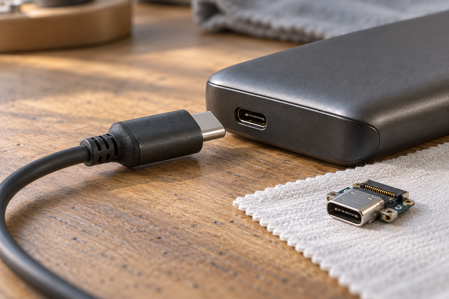
A detachable cable puts one repair boundary in plain sight. The plug can leave the device, and a sound, correctly rated replacement can take the damaged cable's place. A captive lead, permanently attached to a charger or small appliance, may make the same fault a repair of the entire unit. A socket on the device is another boundary, though less accessible: if its contacts or mounting fail, changing the cable cannot restore it. Repairability depends on where the separable joints are, how they carry a load, and whether replacement parts exist.
The bend before the contacts
The flexible collar at the end of many cables is called strain relief. Its job is to spread bending along a length of jacket instead of concentrating it at the point where conductors meet the plug. Its shape matters because a supple cord and a stiff connector cannot bend in the same way. A collar that merely looks thick tells us little about what happens inside it. The useful evidence is how the assembled cable performs when bent and pulled.
The USB Type-C cable and connector specification, release 2.0, sets a cable-assembly flex test of 100 cycles in each of two planes, with no physical damage or electrical interruption lasting more than one millisecond. It also specifies an axial pull test of 40 newtons for at least one minute. These are defined tests, with a prescribed bend geometry and load. They do not mean that every cable can survive years of being folded sharply against a plug, nor do they reveal the exact construction of an overmould. They do establish that a cable end has to be judged as a mechanical assembly, not just as a row of electrical pins.
The same specification calls for a minimum durability rating of 10,000 insertion and extraction cycles for the Type-C connector family. That figure concerns a prescribed mating test; it is not a promise that an abused port will last for 10,000 ordinary days. The distinction matters to a repair. Replacing a cable repeatedly asks the device's socket to remain sound too. A removable lead can spare the device one kind of failure, while a weak or obstructed receptacle remains its own problem. The USB-IF's later connector and cable compliance document accordingly treats receptacles, plugs and complete cable assemblies as separately tested articles, with mechanical, environmental and electrical criteria.
A contact is an electrical component
The small metal faces inside a connector conduct current only where they meet. Their resistance is part of the power path, alongside the cable conductors and the device's internal connections. More resistance means more voltage lost across that part of the path; at a given current, it also means more heat there. A loose, worn or contaminated joint therefore deserves attention even when the cable jacket looks intact. It does not follow that a warm connector proves a particular defect: temperature depends on current, surroundings and the rest of the design.
The 2019 USB Type-C specification gives a maximum initial low-level resistance of 40 milliohms across a mated plug-and-receptacle contact, under its stated measurement method. That number excludes internal plug and socket substrates. Treating it as the resistance of a whole cable would be a mistake. The broader IEC connector-test specification makes the same methodological point: a product's detail specification must say which tests apply, how severe they are, and what performance limits are permitted. A connector's impressive cycle count or current rating has meaning only with its test conditions attached.
The shape of a plug also cannot certify the cable behind it. The USB specification describes standard Type-C cable assemblies rated for 3 amperes and separately identified, appropriately designed assemblies that may support up to 5 amperes with USB Power Delivery. USB-IF's 2022 cable power-rating logo guide distinguishes certified 60-watt and 240-watt cables and ties those marks to compliance testing. The point for a replacement is modest but important: match the cable's documented power and data capability to the device and charger. A Type-C plug is a common interface, not a universal certificate of electrical performance.
Standard shape, different repair paths
Standardising the external interface widens the field of possible replacement cables. USB-IF describes Type-C as a connector ecosystem with a reversible plug and scalable power and performance. Yet the common outer shape does not dictate how a maker attaches the receptacle to a circuit board or whether the port can be obtained as a spare. Two devices can accept the same cable and offer sharply different repairs when their sockets wear. TE Connectivity's 2025 connector catalogue illustrates the range within one nominal interface: power-only and power-and-signal receptacles, several mounting positions, and sealed and unsealed variants. A standard mating face leaves many design decisions behind it.
A proprietary interface is not automatically a disposable one. Apple's May 2026 support guidance for MagSafe cables names a separately purchasable USB-C-to-MagSafe 3 charging cable and distinguishes it from earlier, incompatible MagSafe generations. In that case the device-end plug is model-specific, but the cable is still replaceable without replacing its power adapter. The limitation lies in compatibility and access to the matching part. The example resists a simple ranking of standard and proprietary connectors: the repair question is whether the failed part can be identified and replaced with one suited to that exact system.
Inside the device, the boundary can move again. Framework's 2025 guide to Expansion Cards shows a user-removable outer port card. If that card is the damaged piece, it can be exchanged without soldering at the board. The design still has an internal connection between card and computer; it has made the exposed port replaceable, not abolished every possible connector fault. Fairphone's August 2026 Gen. 6 repair guide places the USB-C receptacle on a separate part connected beneath the loudspeaker unit by a board-to-board joint. That repair is more involved than swapping a cable or an external card, but the worn socket is not necessarily inseparable from the phone's main electronics. Both examples show that a connector can be a deliberate seam in a product's architecture.
A seam also has to seal
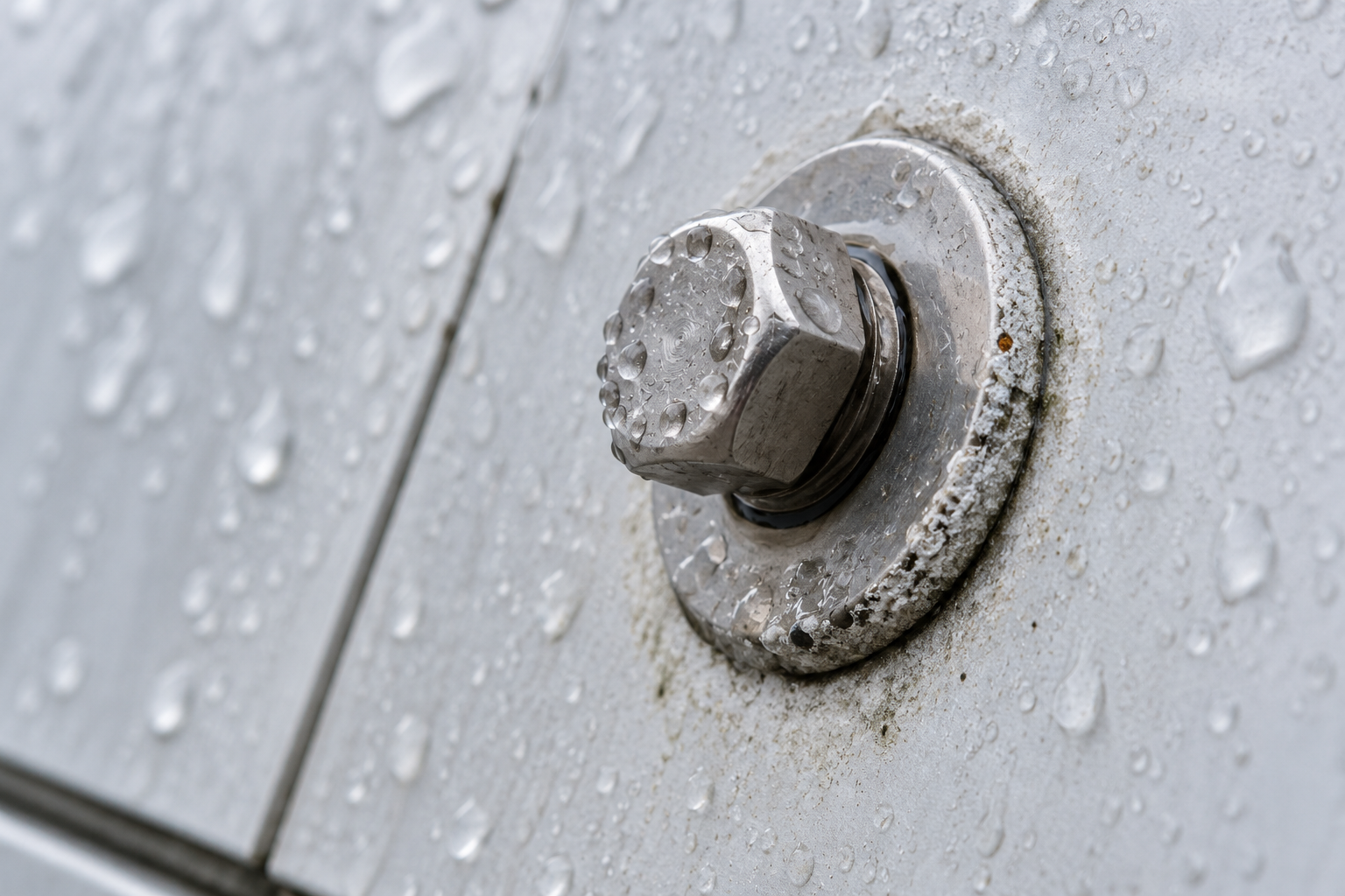
An opening for a plug is an opening the enclosure must manage. The IEC 60529 IP Code classifies protection provided by an equipment enclosure; it is not a blanket description of every loose component inside. TE's 2025 catalogue lists Type-C receptacles sold as sealable to different water-ingress ratings alongside versions with no such rating. That catalogue establishes that sealing can be designed around a standard port. It does not prove that a device using any one of those parts has the same rating, or that its rating survives a careless reassembly. The gasket, case joint and installation all belong to the finished enclosure.
This is the real design tension. A permanently bonded joint can simplify some sealing and packaging decisions; a removable module needs a joint that can be opened, rejoined and kept in the intended condition. The presence of screws or a board connector alone does not settle the water question. Nor does water resistance by itself tell us whether a port is replaceable. The maker has to specify both the repair path and the enclosure performance, and a repair should follow that model's instructions when either matters.
The best connector is therefore not the one with the largest advertised cycle count or the most familiar outline. It is a sound, correctly rated contact placed at a useful boundary: a cable that can leave a charger, a port that can leave a device, a strain relief that keeps ordinary bending away from delicate terminations, and an enclosure whose protection is accounted for when that boundary is crossed. When the cable end finally gives way, those quiet decisions determine how much else must go with it.
A thought worth keeping?