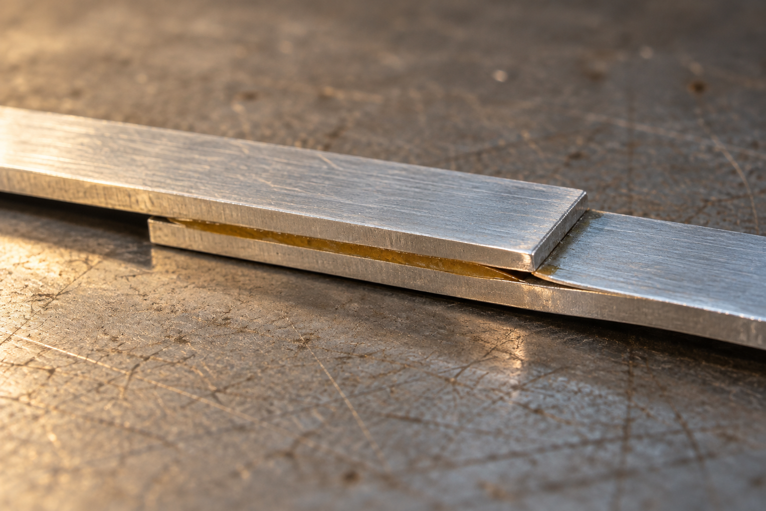
Two strips of metal can be glued across a generous overlap, then part first at one narrow end. The result can look like a failure of the adhesive over the whole area. In a loaded lap joint, however, the load does not visit every millimeter of glue equally. It enters the bonded region at an edge, passes from one strip through the adhesive into the other, and leaves at the opposite edge. The middle may have ample area while an end carries a sharp concentration of work.
This is a structural question, not a test of whether a particular brand of glue is “strong.” In a 1973 technical report for NASA, L. J. Hart-Smith analyzed single-lap joints and showed how their offset load path bends the joined strips. His calculations treated adhesive shear, peel and the possibility that the adhesive can yield rather than remain perfectly elastic. They also showed that a metal strip could begin to yield near a joint end before the adhesive exhausted its own capacity; in a composite, the material beneath the bond could split. The first visible crack does not by itself name the weakest ingredient. NASA single-lap report
The load arrives at an edge
Imagine two flat rulers overlapping, one above the other, pulled at their free ends. Their center lines do not line up. The pull therefore tends to rotate the overlap as well as slide one ruler past the other. Sliding loads the adhesive in shear. Rotation tries to lift the strips apart at an end, adding peel: tension across the bond rather than along it. The exact pattern depends on strip stiffness, adhesive thickness, geometry and how the joint is held. A larger glued rectangle cannot be treated as though every square millimeter shares an identical portion of the force. NASA analysis · 2003 aluminium-joint study
An analytical study of symmetrical double-lap joints makes the edge problem clearer. Putting a central strip between two outer strips reduces the bending that a single offset lap experiences. Yet the researchers still calculated steep rises in adhesive shear and peel stresses toward the ends of the bonded region. Symmetry addresses one source of trouble without making stress uniform. It also matters whether the tensile peel stress lands on one end while the other is locally compressed; the two ends are not always interchangeable. Double-lap stress analysis
Models become more persuasive when an experiment watches a joint move. In tests of dissimilar aluminium and carbon-fiber single-lap joints, researchers used digital image correlation to follow local deformation while the specimens were pulled. Their measurements placed important peeling strains toward an overlap extremity where failure began. The carbon-fiber material itself could delaminate or pull out, reducing joint strength. That is different from all of the glue simply separating cleanly from a metal surface. Dissimilar-joint experiment
Wood offers another revealing failure surface. A 2024 experiment on bonded wood single-lap joints observed cracks starting near the overlap edge between wood layers, while its model indicated little damage in the adhesive layer. The joint failed, but the glue was not necessarily what failed first. Edge stresses found a route through the nearby material. This does not make every wood glue joint an edge failure; it shows why fracture location and the broken surfaces must be examined together. Wood lap-joint study
Move the concentration, and the failure may move
One response is to change how stiffness is distributed along the overlap. In a 2003 test of aluminium single-lap joints, researchers used a stiffer adhesive in the middle and a more compliant adhesive near the ends. Their experimental joints carried more load than the tested joints made with either single adhesive along the entire overlap. The flexible ends could deform more and ease the stress concentration there. It was a designed, tested arrangement with particular aluminium strips and adhesives, not a general instruction to mix two household glues. Aluminium bi-adhesive study
Moving the stress does not abolish it. A later experimental study used image correlation to map strains along joints made with both stiff and flexible adhesives. Under its combinations of thickness and material, failure began at the boundary between the two adhesives and then ran into the brittle one. The researchers also found that changing the flexible region's length affected peel strain differently as adhesive thickness and strip stiffness changed. A design that protects a free edge can create a new transition that deserves its own examination. 2020 bi-adhesive experiment
The design of the strips matters alongside the adhesive. A stiff adherend bends differently from a thin flexible one; two dissimilar adherends can concentrate load asymmetrically. In the double-lap analysis, balancing the geometry reduced one kind of eccentric bending but left end effects. In Hart-Smith's single-lap analysis, adhesive yielding could spread load that a purely elastic model had piled too sharply at an end. That is why a simple calculation of bond area multiplied by a glue's advertised strength can be misleading. The joint is a system of materials and a path for force, not a flat sticker under a perfectly even pull. NASA analysis · Double-lap analysis
Other failures are possible. Poor surface preparation, water, heat, repeated loading and defects can alter a real bond, and the experiments above do not measure all of those histories. Nor do they show that every edge crack will grow. What they do establish is why an edge deserves attention even when a bond looks broad and clean: it is where the load begins to cross between pieces, where bending can try to lift them, and where the material next to the glue may be asked to carry more than its share. A joint's strength lives in that transfer, not in its area alone.
A thought worth keeping?